bad sector
- Beiträge
- 40
- Likes
- 12
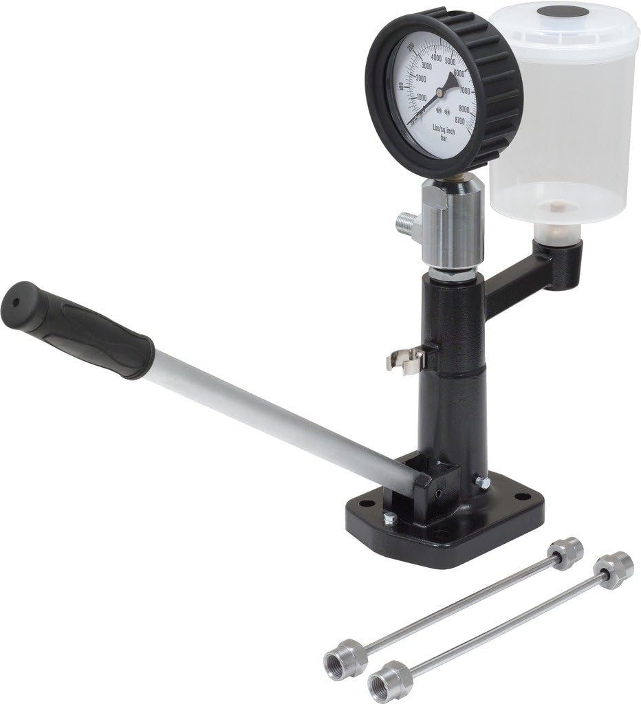
My european model (rare in Canada) 1991 Dx-6.05 is coming along slowly. The engine is close to 'rollout' but I'm stuck with the injection drip-timing. The procedure in 'the book' shows a small hi-pressure hand-pump being used but doesn't say boo about the acceptable pressure-range!

The only such pump I have is an injector testing pump that's good for 9000psi and that could be overkill ..it could also destroy the injection-pump.
I've been looking around for such a pump but can't find any, of course not knowing the pressure-range doesn't help either.
Anyone know that pressure-range and where such pumps are sold (in 2024)? I'm also not sure about the exact sequence of what to expect seeing coming out of the drip-tube:
- when is there flow
- when is there nothing
- when is there a first drop or a last drop.
Thank you.
")